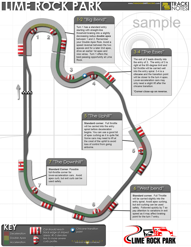
This page contains the complete Lime Rock Park Track Notes so you can learn how to use Track Notes and see what they have to offer.
| Click here to download a PDF version of the Lime Rock Park Track Notes or scroll down to view them online | |
| File Size: | 2642 kb |
| File Type: | |
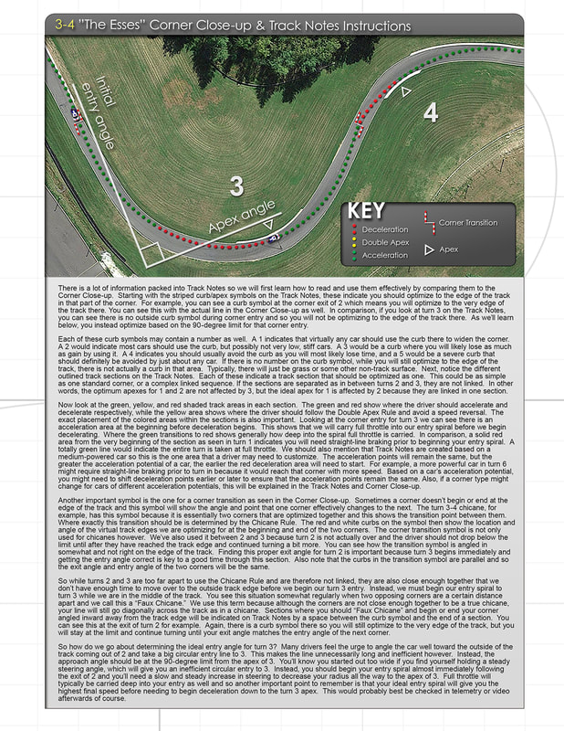
There is a lot of information packed into Track Notes so we will first learn how to read and use them effectively by comparing them to the Corner Close-up. Starting with the striped curb/apex symbols on the Track Notes, these indicate you should optimize to the edge of the track in that part of the corner. For example, you can see a curb symbol at the corner exit of 2 which means you will optimize to the very edge of the track there. You can see this with the actual line in the Corner Close-up as well. In comparison, if you look at turn 3 on the Track Notes, you can see there is no outside curb symbol during corner entry and so you will not be optimizing to the edge of the track there. As we’ll learn below, you instead optimize based on the 90-degree limit for that corner entry.
Each of these curb symbols may contain a number as well. A 1 indicates that virtually any car should use the curb there to widen the corner. A 2 would indicate most cars should use the curb, but possibly not very low, stiff cars. A 3 would be a curb where you will likely lose as much as gain by using it. A 4 indicates you should usually avoid the curb as you will most likely lose time, and a 5 would be a severe curb that should definitely be avoided by just about any car. If there is no number on the curb symbol, while you will still optimize to the edge of the track, there is not actually a curb in that area. Typically, there will just be grass or some other non-track surface. Next, notice the different outlined track sections on the Track Notes. Each of these indicate a track section that should be optimized as one. This could be as simple as one standard corner, or a complex linked sequence. If the sections are separated as in between turns 2 and 3, they are not linked. In other words, the optimum apexes for 1 and 2 are not affected by 3, but the ideal apex for 1 is affected by 2 because they are linked in one section.
Now look at the green, yellow, and red shaded track areas in each section. The green and red show where the driver should accelerate and decelerate respectively, while the yellow area shows where the driver should follow the Double Apex Rule and avoid a speed reversal. The exact placement of the colored areas within the sections is also important. Looking at the corner entry for turn 3 we can see there is an acceleration area at the beginning before deceleration begins. This shows that we will carry full throttle into our entry spiral before we begin decelerating. Where the green transitions to red shows generally how deep into the spiral full throttle is carried. In comparison, a solid red area from the very beginning of the section as seen in turn 1 indicates you will need straight-line braking prior to beginning your entry spiral. A totally green line would indicate the entire turn is taken at full throttle. We should also mention that Track Notes are created based on a medium-powered car so this is the one area that a driver may need to customize. The acceleration points will remain the same, but the greater the acceleration potential of a car, the earlier the red deceleration area will need to start. For example, a more powerful car in turn 6 might require straight-line braking prior to turn in because it would reach that corner with more speed. Based on a car’s acceleration potential, you might need to shift deceleration points earlier or later to ensure that the acceleration points remain the same. Also, if a corner type might change for cars of different acceleration potentials, this will be explained in the Track Notes and Corner Close-up.
Another important symbol is the one for a corner transition as seen in the Corner Close-up. Sometimes a corner doesn’t begin or end at the edge of the track and this symbol will show the angle and point that one corner effectively changes to the next. The turn 3-4 chicane, for example, has this symbol because it is essentially two corners that are optimized together and this shows the transition point between them. Where exactly this transition should be is determined by the Chicane Rule. The red and white curbs on the symbol then show the location and angle of the virtual track edges we are optimizing for at the beginning and end of the two corners. The corner transition symbol is not only used for chicanes however. We’ve also used it between 2 and 3 because turn 2 is not actually over and the driver should not drop below the limit until after they have reached the track edge and continued turning a bit more. You can see how the transition symbol is angled in somewhat and not right on the edge of the track. Finding this proper exit angle for turn 2 is important because turn 3 begins immediately and getting the entry angle correct is key to a good time through this section. Also note that the curbs in the transition symbol are parallel and so the exit angle and entry angle of the two corners will be the same.
So while turns 2 and 3 are too far apart to use the Chicane Rule and are therefore not linked, they are also close enough together that we don’t have enough time to move over to the outside track edge before we begin our turn 3 entry. Instead, we must begin our entry spiral to turn 3 while we are in the middle of the track. You see this situation somewhat regularly when two opposing corners are a certain distance apart and we call this a “Faux Chicane.” We use this term because although the corners are not close enough together to be a true chicane, your line will still go diagonally across the track as in a chicane. Sections where you should “Faux Chicane” and begin or end your corner angled inward away from the track edge will be indicated on Track Notes by a space between the curb symbol and the end of a section. You can see this at the exit of turn 2 for example. Again, there is a curb symbol there so you will still optimize to the very edge of the track, but you will stay at the limit and continue turning until your exit angle matches the entry angle of the next corner.
So how do we go about determining the ideal entry angle for turn 3? Many drivers feel the urge to angle the car well toward the outside of the track coming out of 2 and take a big circular entry line to 3. This makes the line unnecessarily long and inefficient however. Instead, the approach angle should be at the 90-degree limit from the apex of 3. You’ll know you started out too wide if you find yourself holding a steady steering angle, which will give you an inefficient circular entry to 3. Instead, you should begin your entry spiral almost immediately following the exit of 2 and you’ll need a slow and steady increase in steering to decrease your radius all the way to the apex of 3. Full throttle will typically be carried deep into your entry as well and so another important point to remember is that your ideal entry spiral will give you the highest final speed before needing to begin deceleration down to the turn 3 apex. This would probably best be checked in telemetry or video afterwards of course.
Front
Reverse
|
Shortly after completing work on the Science of Speed Series books, Adam Brouillard created the following demonstration video. In it, he shows how, through training and an understanding of the proper goals, he was able to not only greatly improve upon his own previous times, but also improve upon the time set by a professional sim-racer and GT Academy finalist.
|
|
Additional Reference Laps Below
|
|
Here is an updated video of the MX-5 at Lime Rock Park. Notice how Adam needs a lift after the chicane transition prior to the apex of turn 4, which in the previous video he mentions would likely be necessary to fully optimizing that section.
|
|
|
|
|
|
|
